The Charlieplexing technique is named after its inventor, Charlie Allen, who invented the technique in 1995.
Most of the notes below came from a quick look at Charlieplexing by Brian Lough and Christmas Lights Special - Microcontroller Basics (PIC10F200) at circuitbread.com
Controlling a light-emitting diode (LED) is the hello world of electronics. Its often the first simple circuit we create.
The problem with doing this is it teaches us we need one General Purpose Input/Output (GPIO) pin to control something simple like our LED. For a Raspberry Pi which has 40 pins, 26 are GPIO so thats atleast 26 LEDs.
What if you need to control other things with those GPIO’s on the Pi or you have a much simpler micro controller such as the PIC10F200. The PIC10F200 only has 8 pins, of which 3 are GPIO so we would assume it can only control 3 LEDs.
With Charlieplexing it can in-fact control 6.
This is calculated with N * (N - 1) where N is the number of GPIO pins your controller has
1 | N * (N - 1) |
How does this work?
I drew these diagrams using https://www.circuit-diagram.org/
For every pair of GPIO there are 2 LEDs placed in operside polarity, LEDs will only work when the current flows from their positive to negative. Charlieplexing exploits this so the LED can be connected in a circuit.
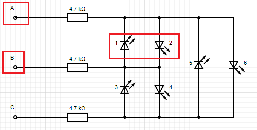
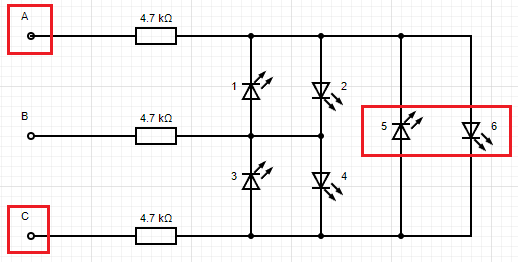
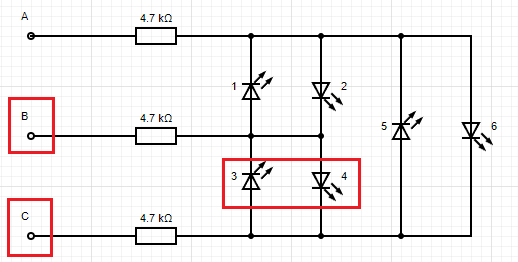
Using the diagrams above we will need to set the polaritys as follows to light up each LED (one at a time).
GPIO can be one of 3 states:
high voltagelow voltageHigh z / high impedance- High z can be achieved by setting the pin as
INPUT - High z is often marked as
Zin tables for Charlieplexing
- High z can be achieved by setting the pin as
The truth table below shows the states above. Note that these diagrams show 1 resistor per wire but if the LEDs were all different colours they could have their own resistors to accommodate the voltage drop.
1 | A | B | C | #LED |
4 GPIO
This would be 4 * (4 - 1) = 12 LEDs
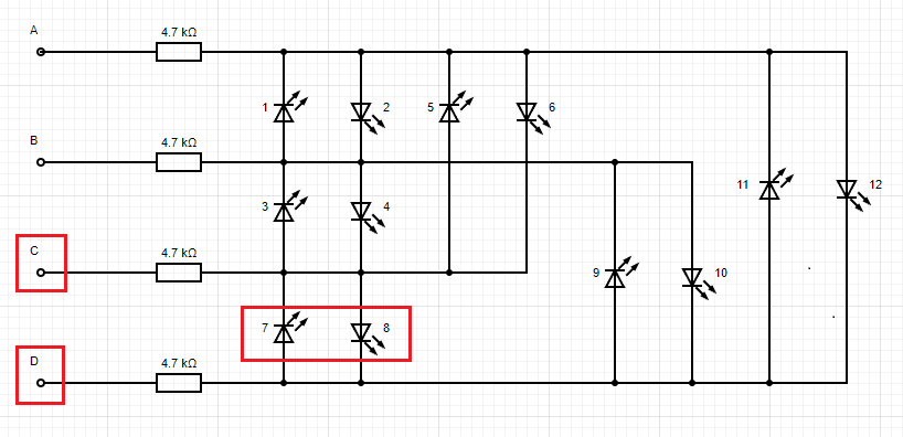
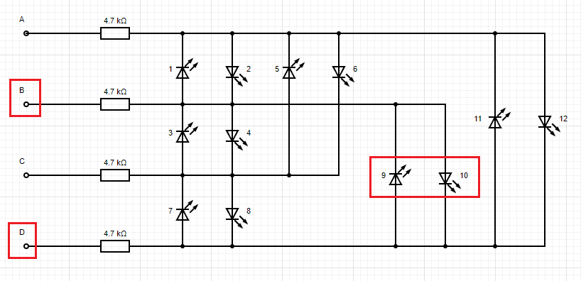
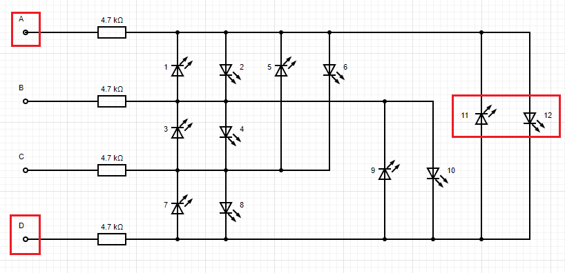
Truth table expanding from the GPIO 3 table.
1 | A | B | C | D | #LED |