These are notes I made while watching the amazing tutorials from Circuit Bread and circuitbread.com
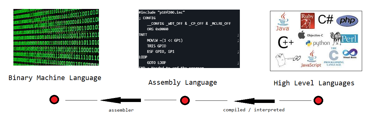
Assembly Code
In computer programming, assembly language (or assembler language), is any low-level programming language in which there is a very strong correspondence between the instructions in the language and the architecture’s machine code instructions. - wikipedia.org
Four main parts of Assembly
labels- is a section of the code, partially for the human to understand what is going on. Can also be used as a reference within the codeinstructions- its a way of taking a word and shortening it up using a subset of letters (often the first letters of the word). This then reperesents something so you dont have to type out the whole word/sentence each time. These are also known asnumonics/operational codeoperands- these are the parameters that you give yourinstructionscomments- human readable words to understand what the program is doing
Instruction examples
1 | BSF - Bit Set F. A set bit makes a pin high and clear bit makes a pin low |
Hardware & Software
Some key terms and notes
ICis integrated circuit (its the microcontroller)PCis the Program Counter which is where you are in the program (feels like the stack in .net)stackthis small PIC10F200 has two levels of stack used to store the memory addresses when calling sub routines like aGOTO
There are many microcontrollers on the market and each vendor has proprietary and often trade marked technologies. Most of my notes are on PIC10F200 microcontroller by microchip. Others I found online are
- Atmel
- PIC12F675 (microchip)
- PIC16F88 (microchip)
PIC10F200
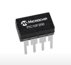
- Voltage range is 2.0V to 5.5v
- 16 bytes RAM (10 -> 1F)
- 4 mHz / 4 ticks
- 256 words (instructions) as 12 bits = 1 word
1 | 256 * 12 / 8 (bytes) |
Logical pins:
1 | ------ |
N/Cno connect, so nothing is connected to these pinsVDDpower+GP0,GP1,GP2general-purpose input/outputT0CKIGP3input onlyMCLR (bar)the bar is the line above MCLR, it means high its inversed so set to low to clearVSSground-ICSPDATin-circuit serial programming Data (PICKit connection)ICSPCLKin-circuit serial programming Clock (PICKit connection)
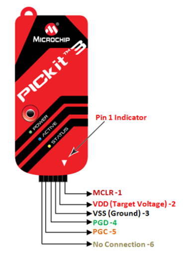
PICKit 3 / PICKit 4
This is the programmer / debugger (The ICD series are the more expensive none hobby ones). This this post at vlrobotech.com has details about the PICKit 3 and a cool 35 light control project!
You can also use an arduino as the programmer but I found a cheap PICKit 3 locally so rolled with it.
1 | 1 VPP/MCLR clear |
MPLAB X / 8.7x
This is the the Integrated Development Environment (IDE)
I could get the sample code to work with v8.7
1 | Project -> New |
I had no luck with MPLAB X
Projects
These are the simple projects involving LEDs that noobs like me can understand! (kind of)