A servo allows precise control of the angular position of its shaft. Standard servos accept 4.6 to 6 volts.
| Colour | Description |
|---|---|
| Yellow/White | Control signal |
| Red | Positive power lead |
| Black/Brown | Negative power lead |
Control signal
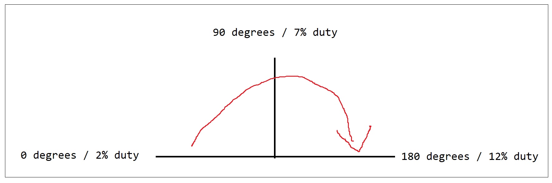
This needs to be a pulse width modulation (PWM) square wave. The square wave needs to be 50 herts (so a pulse of every 0.2 seconds) The angle of the servo is controlled by the length of the positive pulse (duty cycle) The longer the pulse/period of the wave/duty cycle the larger the angle the servo will turn to and try hold itself at.
These values vary by servo but for the small cheap SG-90’s the degrees can be calculated as:
1 | 2% duty cycle = 0 degrees |
Translating this to python code using the RPi.GPIO library
1 | import RPi.GPIO as GPIO |
References
- https://sourceforge.net/p/raspberry-gpio-python/wiki/PWM/
- https://www.servocity.com/how-does-a-servo-work
- http://www.robotplatform.com/knowledge/servo/servo_control_tutorial.html
- http://webhome.csc.uvic.ca/~mcheng/samples/qu/SENG466_Home/Phase_1/Entries/2010/2/1_Servo_Motor.html
- https://www.youtube.com/watch?v=xHDT4CwjUQE