Fundamentals at 2D level in Fusion 360 using basic shaped., we would use the X (red) and Y (green) plains and the 3D printer will extrude into Z (blue). Create - > Create Scetch and the select the plain between red and green.
We need to be deliberate about position and dimension so that the sketch always has the little red lock indicating its fully constrained and the object we added goes black (and not blue).
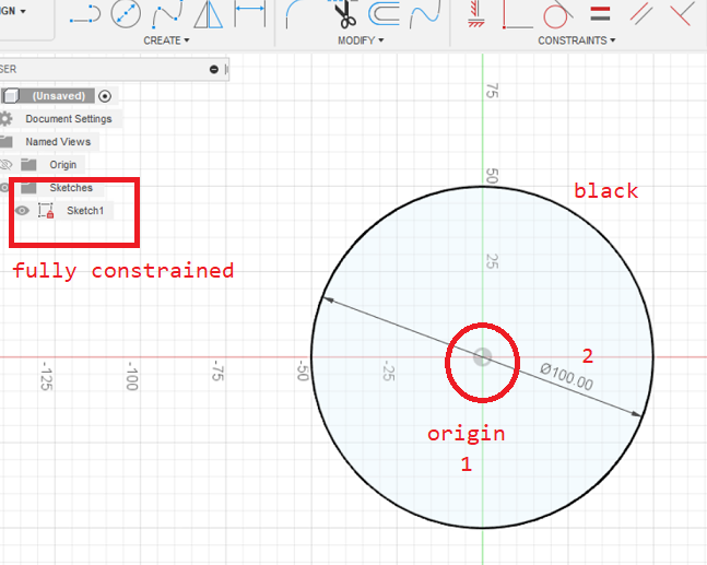
Circle (at origin)
CREATE - > Circle -> Center Diameter Circle -> select position (origin) -> provide dimension.
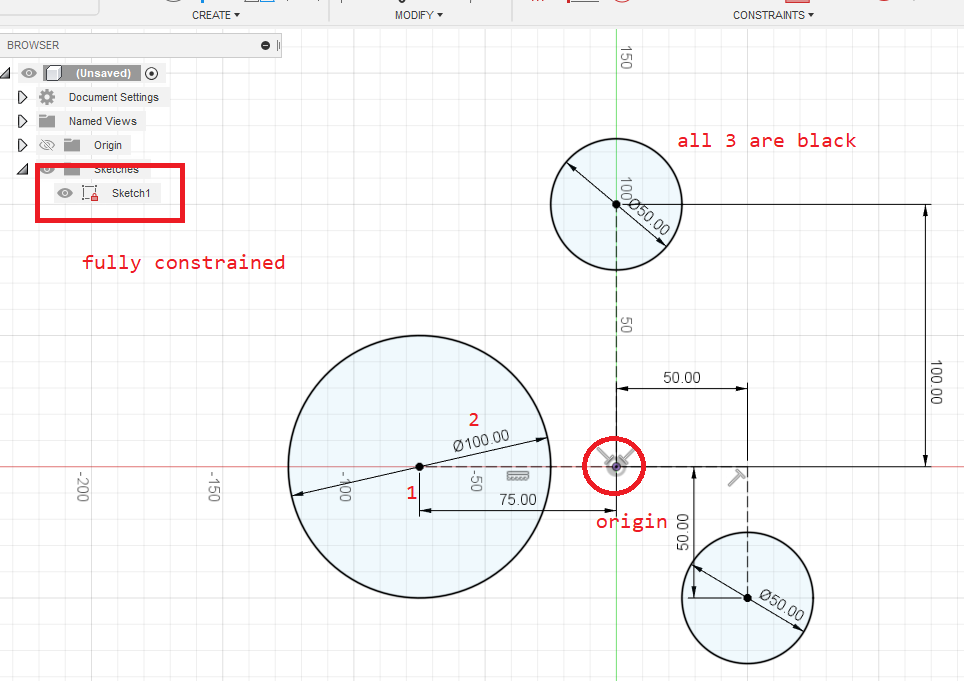
Circle (on construction lines)
CREATE - > Line -> set line type construction -> select position (origin) -> align to plain (red or green) -> provide dimension.
CREATE - > Circle -> select construction line position -> provide dimension.
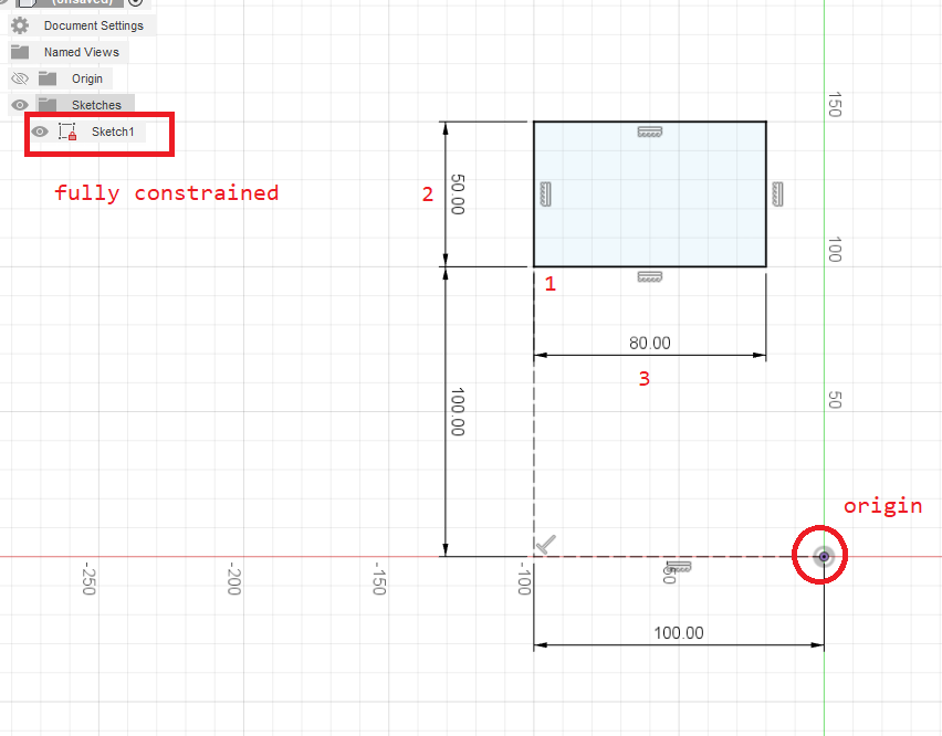
Rectangle
CREATE - > Line -> set line type construction -> select position (origin) -> align to plain (red or green) -> provide dimension.
CREATE - > Rectangle -> 2 Point Rectangle -> select construction line position -> provide dimension -> tab -> provide 2nd dimension
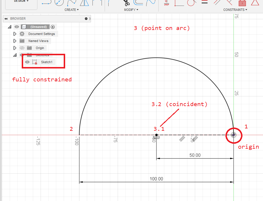
Arc (from origin along construction line)
Create 2 constructions lines along red, 100mm and 50mm
CREATE - > Arc -> 3 Point Arc -> select origin -> select the end of the 100mm construction line
Create constraint of type coincident
CONSTRAINT -> Coincident -> select the end of the 50mm construction line -> select the center point of the arc
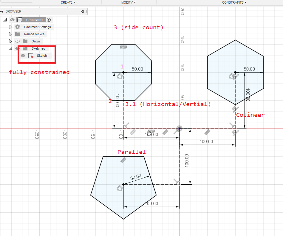
Polygon
Create construction lines simliar to the above
CREATE - > Polygon -> Circumscribed Polygon -> select the construction line point -> drag and set the radius -> tab and set the amount of sides. Repeat and create another 2 polygons to the right and below
Create constraint of type Horizontal/Vertial (for the first polygon)
Select the polygons top line -> select CONSTRAINT -> Horizontal/Vertial
Create constraint of type Colinear
CONSTRAINT -> Colinear -> select point in the middle of the polygon -> select a corner of the polygon -> select point of construction line outside of the polygon
Create constraint of type Parallel
CONSTRAINT -> Parallel -> select a line from the polygon -> select a construction line
Circumscribed (outside the circle) | Inscribed (inside the circle)
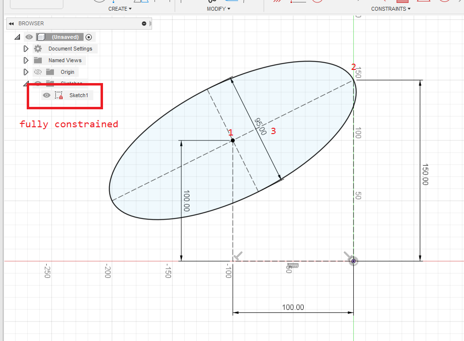
Ellipse
CREATE - > Ellipse -> select the construction line point [1] -> release and select the tip of the at the next construction line [2] -> set the dimension [3]
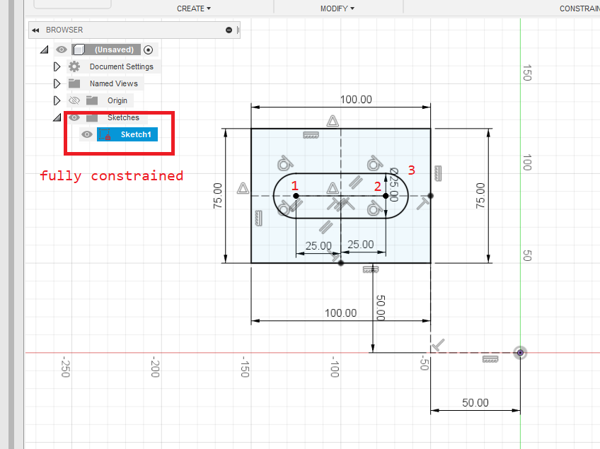
Slot
Requires a square with 2 construction lines deviding it into 4 equal parts, then from the center 2 additional construction lines (these are the 25mm ones)
CREATE - > Slot -> Center to Center Slot -> select construction line point [1] -> release and select construction line point [2] -> then set the dimension (this is the 25mm radius)
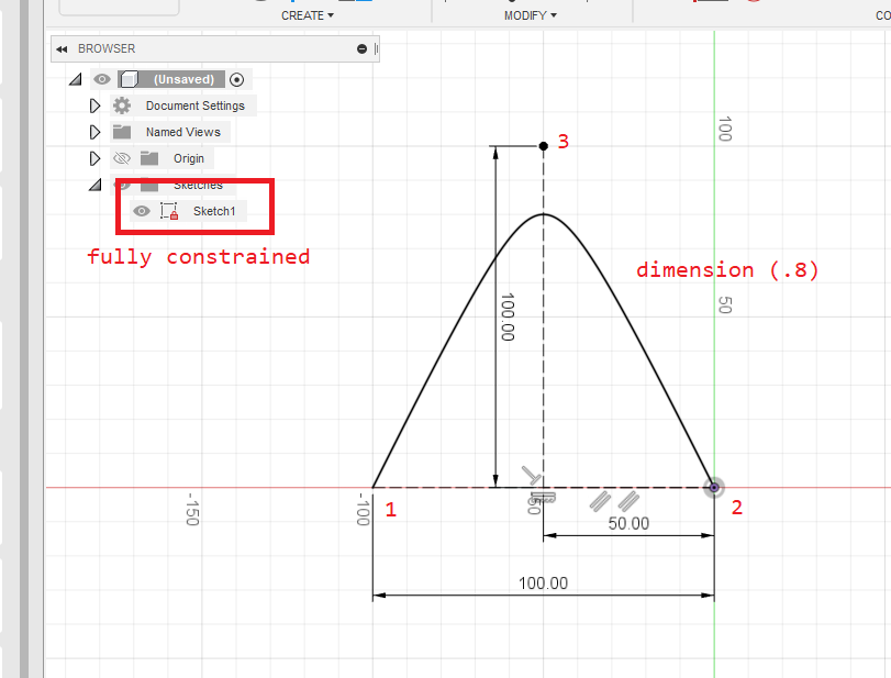
Conic Curve
Requires the 3 construction lines shown as 100.00, 100.00 and 50.00
CREATE - > Conic Curve -> select construction line at point [1] -> construction line at point [2] -> then construction line at point [3] -> then set the dimension
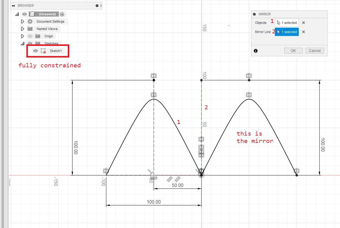
Mirror
This mirrors the selection and applys any new changes automagically. Here I mirrored the conic curve above.
CREATE - > Mirrow -> select the object (can be any object) at [1] -> select the line at [2] -> the mirror then appears on the right
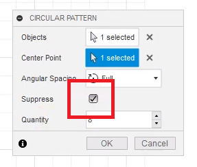
Circular Pattern
This requires 1 construction line and then the object to create in a circular pattern.
CREATE - > Circular Pattern -> select the object at [1] -> select the center point at [2] -> set the quantity and click ok
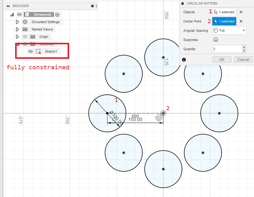
Can also create pattern with missing elements by selecting suppress and then unchecking elements