Building on the Microcontrollers and Assembly Code post this is my first project based on the amazing work from circuitbread.com.
Turning on a LED (Hello World)
- Getting Started with MPLAB X IDE - Part 4 Microcontroller Basics (PIC10F200)
- Your First Assembly Program - Part 5 Microcontroller Basics (PIC10F200)
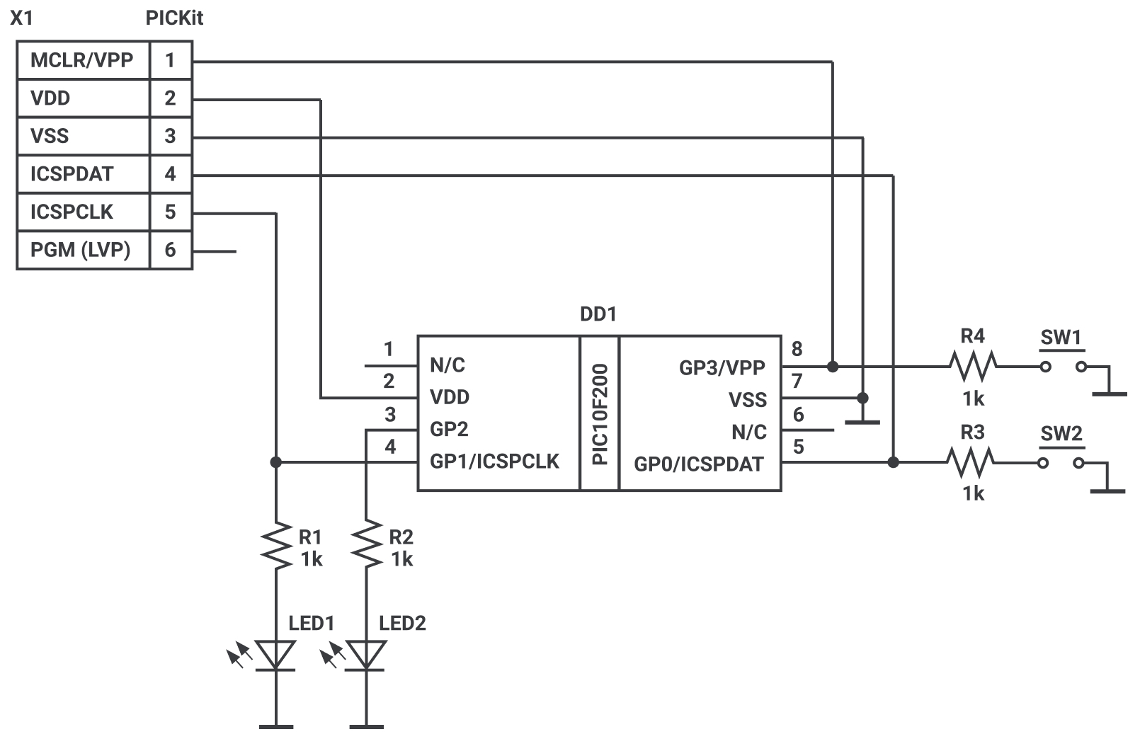
Diagram from circuitbread.com
1 | #include "p10f200.inc" |
#include "p10f200.inc"tells the IDE & compiler there are parameters already pre-defined for the chip that we can include, things like theGP2which would reference the bit in the register for us; CONFIGthis is comment telling the human we are going to do the configuration__CONFIGsetup the micro controller (p10f200)_WDT_OFFwatch dog timer off (else it will reset itself every once in a while)_CP_OFFcode protection off_MCLRE_OFFmeans we can use pin 8 as a GP input and not a reset pin
ORG 0x0000origin, this is the begin of the program to executeINIT ; We are initializing the microcontroller over the next three lines.- this is aINITis alabeltelling us where we will initialize / setup the controller anything after the;is a human readable commentMOVLW ~(1 << GP2)MOVLWis aninstructionwhich moves the literals you pass it to the working register- the tilda
~is a bitwise operations that inverts 1 and 0s. IE: 1 becomes 0 and 0 becomes 1 - the left shit
<<takes what we have and shifts it to the left
1 | bits 7 6 5 4 3 2 1 0 |
TRIS GPIOtheTRISinstructionalways takesGPIOas anoperand. It meansTriStateso the GPIO can behigh voltage,low voltageorhigh impedance (OFF). This means take the values we put in the register and load them into theTRISGPIO. SoGP2is an output because its value is0BSF GPIO, GP2- set the bit in the register, this is setting GP2 to1/HIGHturning on the LEDLOOP- just a lableGOTO LOOP- go back to the loop above, which will jump down toGOTO LOOP, so this is an infinite loopEND- the end of our program